Bolted connections are ubiquitous in everything from the high-tech mechanisms that ESR designs for spacecraft through to the hobby projects and 3D-printed widgets many of our engineers make at home. But even many mechanical engineering professionals aren’t familiar with the full level of complexity of bolted joints. Through our work in failure analysis, we are well-acquainted with the common reasons for failure of bolted joints such as shear-out and thread stripping, as well as a few subtler ones. This article will look at a few of the less well understood root causes of bolt failures.
Lubrication
Fundamentally, a screw thread is a wedge that is driven between two members to generate a clamping force. Thinking about it like this, it’s clear that friction, and hence lubrication, is a key factor in the efficiency of the conversion of how hard we push the wedge – torque in the case of a bolt – to how hard the bolted members are compressed (and equivalently, the tension in the bolt). In the context of bolted joints, we call the coefficient of friction the nut factor.
In most applications, a lack of lubrication applied to a bolted joint will result in inadequate preload and reduced joint stiffness. However, in some applications, for example some automotive wheel lugs, the specified torque may be based on dry (unlubricated) threads, and in such situations addition of lubrication can result in bolt over-tightening, and even strip out or yield. For this reason, it is vital to know both the torque to be applied and the specified lubricant in order to correctly assemble the joint.
Poor torque sequence
Torquing can make or break a bolted connection – literally! Most engineers are familiar with the star pattern for tightening lug nuts or a flange, but for some demanding applications, multi-stage torque sequences are required to ensure one side of the joint is not over-stressed. Some torque sequences even involve multiple rounds of tightening and loosening to smooth the surface finish on the mating parts, which brings us to the next item.
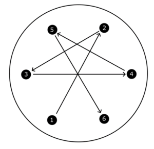
Figure 1 Star-pattern torque sequence for a six-bolt flange.
Poor surface finish
Real surfaces are not perfectly flat. When two parts make contact with each other, they are in fact only touching at the microscopic high spots (asperities) on their surfaces. Once a bolt is tightened, these asperities will start to bed down over time. This is “settlement”, it may cause relaxation of the bolt tension (preload) and can be especially problematic in cases of fatigue loading, as asperities are flattened down over multiple stress cycles.
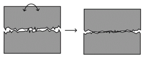
Figure 2 Asperities are flattened, resulting in settlement.
Inadequate or uneven flange compression
We often use bolted connections to make face or flange seals. These might contain an elastomeric O-ring, or for high-vacuum applications, even a metal gasket. In these applications, it is important to make sure that bolts are positioned to ensure the clamping pressure is sufficient all around the joint face. There are a few rules-of-thumb that engineers can use in most cases, as well as design handbooks, but in more unusual or critical cases, it’s best to use finite element analysis to check bolt patterns. Simulation of bolted joints is a complex task involving multiple sources of non-linearity, so these simulations need to be undertaken by experienced analysts.
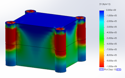
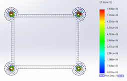
Figure 3 FEA results of normal stress and contact stress for a poorly designed bolted enclosure. Note the low contact stress away from the bolted corners.
Misaligned clamped faces
When a bolted connection is made between two plates, the inside faces are pushed together by the bolts pressing against the outside faces. Because they are pushed together, the two inside faces align parallel to each other. Therefore, if the inside and outside faces of the plate are out-of-parallel, the bolt won’t sit flat against the plate.
Not only will this misalignment lead to additional contact pressure under the bolt head, but it will also set up undesirable bending forces in the bolt. This will both reduce the clamping force on the joint, which could lead to joint movement, and also increase the stresses in the bolt itself.
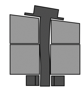
Figure 4 Schematic section illustrating the bending set up in a bolt with a misaligned spot face.
Problems with bolts or looking for failure analysis support?
ESR Technology’s NCT Team have a wealth of experience in designing and trouble-shooting bolted joints, as well as carrying out failure analysis and prescribing remedial action once a defect has been identified. Write to us at info@esrtechnology.com to set up an initial consultation.